Ortho ready (L1C)
Product description
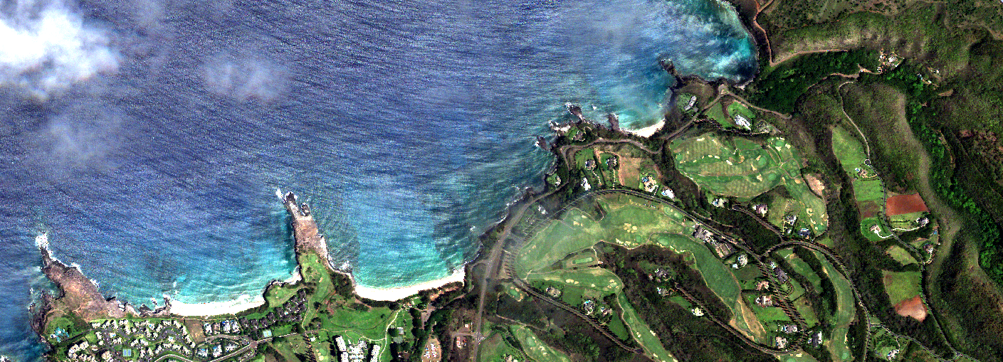
The Ortho Ready (L1C) product is a 4-band imagery dataset designed for users who wish to perform their own orthorectification using a Digital Elevation Model (DEM) of their choice. The 16-bit, 4-band rasters (visual and near-infrared) are provided with Rational Polynomial Coefficients (RPCs). By combining the imagery, the RPCs, and a DEM, users can generate their own geometrically corrected, orthorectified images.
The product includes two main components: the image raster and its corresponding RPCs. The raster is delivered in GeoTIFF format, while the RPCs are conveniently duplicated for maximum compatibility. They are included as both embedded GeoTIFF tags within the raster and as a separate text file (e.g., image.tif and image_rpc.txt)1. This duplication ensures support across major GIS software, as some applications handle one format but not the other.
The RPCs are generated through a rigorous process. First, Ground Control Points are computed on the images against a reference2. A bundle block adjustment is then performed to minimize error and refine the satellite's position and orientation. The resulting physical sensor model is transformed into the simplified RPC polynomial format.
Each L1C raster has a fixed size that depends on the satellite generation (currently MarkIV and MarkV). The nominal ground resolution is also dependent on the satellite generation, orbit altitude, and the off-nadir angle of the capture. A single scene is delivered as multiple L1C images, with each image having a minimum overlap of 10% with the next.
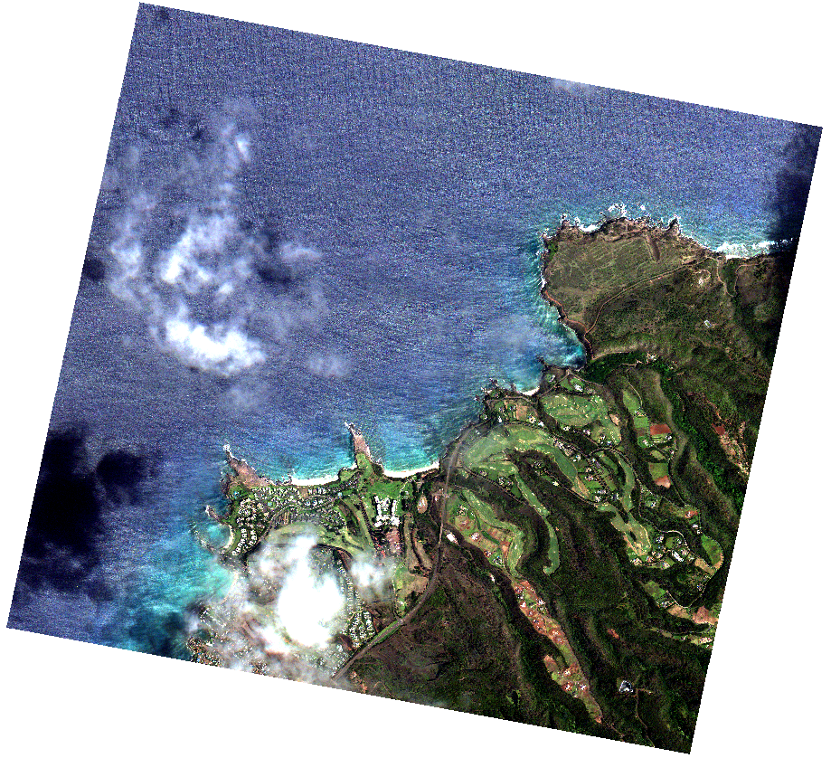 An MarkIV L1C raster example.
Ortho ready product level is composed by a collection of anchor frames, these frames are 4-bands stacked images that contain continuous spectral information. With the available spectral and geometrical information the anchor frames or composites are constructed.
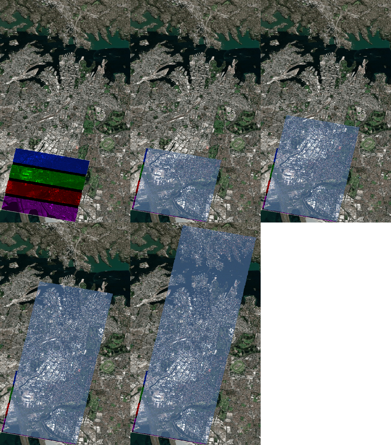 L1C product coverage.
Technical characteristics
| Parameter | Mark IV |
Mark V |
|
|---|---|---|---|
| Spectral bands | Blue : 450 - 510 nm |
Blue : 450 - 517 nm |
|
| Frame size | 5120 x 5120 pix |
7000 x 9344 pix |
|
| GSD | 1.03m 3 |
0.73m 3 |
|
| Swath | 5.2 Km 3 |
6.9 Km 3 |
|
| Projection | Geographic coordinates at WGS84 |
| |
| Max Off-Nadir angle | ± 25 deg |
| |
| Image size | 5120 x 5120 pixels |
9344 x 7000 pixels |
|
| Image bit depth | Unsigned integer 16-bit |
| |
| Image format | GeoTiff, LZW loseless compression |
| |
STAC item
Each L1C product contains multiple assets as well as metadata.
Assets
Non documented files or parameters should be ignored.
All assets follow the same basename template.
{DATE}_{TIME}_{SECOND_DECIMALS}_{SATELLITE}_{PRODUCT}_{PAYLOAD}_{VERSION}_{SUFFIX}.{EXTENSION}
- DATE: Year(4 digits)month(2 digits)day(2 digits)
- TIME: Hour(2 digits)minute(2 digits)second(2 digits)
- SECOND_DECIMALS: All the decimal part from the timestamp seconds
- SATELLITE: Satellite number
- PRODUCT: L1C
- PAYLOAD: MS for multispectral (4 bands)
- VERSION: Check Changelog. Only present in the metadata asset.
- SUFFIX: depends on the asset, can be empty.
- EXTENSION: depends on the asset type.
All time values refer to the capture time in UTC. Hence the string 20220619_153346_938represent actually 2022-06-19 15:33:46.938.
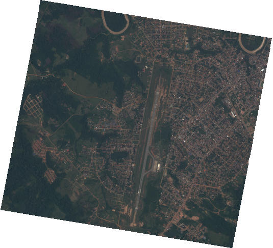
Preview and thumbnail
Raster
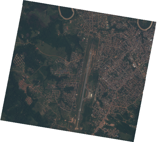 The main raster, also called anchor frame, contains the ready to orthorectify data. It is a fixed size (check Technical specs) 4 bands (RGB and NIR), 16 unsigned bits raster. Its nodata value is 0. Its CRS defined by its RPCs is geographic WGS84. The RPCs are written inside the GeoTIFF as tags 1 and also as a different file in another asset.
The raster format is GeoTIFF with LZW compression.
RPC
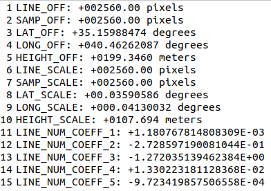 The RPC 4 is a text file with the same name as the raster but having
 analytic_rpc as suffix. This is a common format to store this information that is understood by most software with orthorectification capabilities.
Cloud
Cloud masks are provided as single band GeoTIFFs. Check here for details.

TOA Factors
The L1C product raster is provided in Top Of Atmosphere (TOA) reflectance units (which take values between zero and one), encoded with a 10000 factor in order to fit them in a standard Tiff file. The conversion radiometric conversion factors are inherited from the input images(L1A) processing level.
Item metadata
Metadata is available per anchor frame. Common metadata can be found across composites of the same capture. The following table shows the description of the fields that are always present, together with an example. There may be other fields, but their presence is not guaranteed (most have the prefix satl-insights and satl-qa and correspond to internal image quality measures).
| Prefix | Field Name | Description | Example |
|---|---|---|---|
| n/a | id | Unique identifier for the STAC item | 20250930_025801_143_SN45_L1C_MS_2_0_0 |
| n/a | bbox | Item bounding box | [ 119.56896495671906, 23.62805912936759, 119.65730868533569, 23.690097800133774 ], |
| n/a | assets | List of the assets available for a given item | {
"preview": {
"href": "link to the file",
"type": "image/png",
"roles": [
"overview"
]
},
"rpc": {...},
"cloud": {...},
"analytic": {...},
}
|
| n/a | collection | Collection name | l1c |
| properties | gsd | Ground sample distance in meters | 0.90 |
| properties | eo : cloud_cover" | Percentage of the image covered by clouds | 6.37 |
| properties | proj : shape | Dimension of image in pixels (Height x Width) | [7000, 9344] |
| properties | instruments | Options are MS for multispectral and HS for hyperspectral | ms |
| properties | datetime | Capture time | 2025-09-06T18:43:23.402269+00:00 |
| properties | platform | Satellite name that acquired the imagery | newsat46 |
| properties | proj:epsg | EPSG code of the Coordinate Reference System in which the image coordinates are | 4326 |
| properties | view : azimuth | Viewing azimuth angle. The angle measured from the sub-satellite point (point on the ground below the platform) between the scene center and true north. Measured clockwise from north in degrees (0-360) | 166.1138 |
| properties | view : off_nadir | The angle from the sensor between nadir (straight down) and the scene center. Measured in degrees (0-90). In case this angle cannot be computed, a value of -1 will be reported | 24.9490 |
| properties | view : sun_azimuth | Sun azimuth angle. From the scene center point on the ground, this is the angle between truth north and the sun. Measured clockwise in degrees (0-360) | 72.3332 |
| properties | view : sun_elevation | The estimated sun elevation measured at the target at the moment of the capture. Value in degrees. | 60 |
| properties | satl : satellite_generation | Satellite generation category, mainly to differentiate between MarkIV and MarkV | MarkV |
| properties | satl : outcome_id | The UUID of the entire capture this individual frame is part of | ffbabb4f-3a97-45ec-bca3-0e4d56608c1c |
| properties | satl : valid_pixel | Percentage of pixels that are valid, from 0 to 100 | 100 |
| properties | satl : exposure_sec | Exposure time of capture in seconds | 0.002769 |
| properties | satl : product_name | The product name | L1C |
| properties | satl : last_modified | Timestamp when the product was last processed | 2025-09-30T04:30:38.122305+00:00 |
| properties | satl : transaction_id | Internal processing transaction identifier | l0-pipeline-cw5td |
| properties | satl : product_version | Product Version | 2.1.1 |
| properties | satl : software_version | Internal software version used to process the product | 1.36.1 |
| properties | satl : satellite_altitude | Satellite altitude in meters | 498240.1195991831 |
| properties | satl : ground_lock | Boolean value that indicates if the processor was capable to find gcps at the capture | true |
| properties | satl-qa : qa_software_version | Quality Control project SW version | 2.11.2 |
| properties | satl-qa : snr_blue | Signal To Noise Ratio for the blue band, In case this metric cannot be computed, a value of -999 will be reported | 64.353 |
| properties | satl-qa : snr_green | Signal To Noise Ratio for the green band, In case this metric cannot be computed, a value of -999 will be reported | 56.291 |
| properties | satl-qa : snr_red | Signal To Noise Ratio for the red band, In case this metric cannot be computed, a value of -999 will be reported | 38.133 |
| properties | satl-qa : snr_nir | Signal To Noise Ratio for the NIR band, In case this metric cannot be computed, a value of -999 will be reported | 23.073 |
| properties | satl-qa : burnt_blue | Burnt pixels percentage for the blue band, In case this metric cannot be computed, a value of -999 will be reported | 0 |
| properties | satl-qa : burnt_green | Burnt pixels percentage for the green band, In case this metric cannot be computed, a value of -999 will be reported | 0 |
| properties | satl-qa : burnt_red | Burnt pixels percentage for the red band, In case this metric cannot be computed, a value of -999 will be reported | 0 |
| properties | satl-qa : burnt_nir | Burnt pixels percentage for the NIR band, In case this metric cannot be computed, a value of -999 will be reported | 0 |
| properties | satl-qa : sharpness_fwhm_act_blue | Full Width Half Maximum across-track value in pixels for blue band*, In case this metric cannot be computed, a value of -999 will be reported | -999 |
| properties | satl-qa : sharpness_fwhm_act_green | Full Width Half Maximum across-track value in pixels for green band*, In case this metric cannot be computed, a value of -999 will be reported | 3.675 |
| properties | satl-qa : sharpness_fwhm_act_red | Full Width Half Maximum across-track value in pixels for red band*, In case this metric cannot be computed, a value of -999 will be reported | 3.241 |
| properties | satl-qa : sharpness_fwhm_act_nir | Full Width Half Maximum across-track value in pixels for NIR band*, In case this metric cannot be computed, a value of -999 will be reported | -999 |
| properties | satl-qa : sharpness_fwhm_alt_blue | Full Width Half Maximum along-track value in pixels for blue band*, In case this metric cannot be computed, a value of -999 will be reported | -999 |
| properties | satl-qa : sharpness_fwhm_alt_green | Full Width Half Maximum along-track value in pixels for green band*, In case this metric cannot be computed, a value of -999 will be reported | 3.008 |
| properties | satl-qa : sharpness_fwhm_alt_red | Full Width Half Maximum along-track value in pixels for red band*, In case this metric cannot be computed, a value of -999 will be reported | 2.846 |
| properties | satl-qa : sharpness_fwhm_alt_nir | Full Width Half Maximum along-track value in pixels for NIR band*, In case this metric cannot be computed, a value of -999 will be reported | -999 |
| properties | satl-qa : dr_blue | Dynamic Range for the blue band* *, In case this metric cannot be computed, a value of -999 will be reported | 96.728 |
| properties | satl-qa : dr_green | Dynamic Range for the green band* *, In case this metric cannot be computed, a value of -999 will be reported | 123.545 |
| properties | satl-qa : dr_red | Dynamic Range for the red band* *, In case this metric cannot be computed, a value of -999 will be reported | 150.386 |
| properties | satl-qa : dr_nir | Dynamic Range for the NIR band* *, In case this metric cannot be computed, a value of -999 will be reported | 81.207 |
| properties | satl-qa : alignment_ce95_blue | The 95th percentile of the band-to-band alignment error between the green and blue bands is reported in meters, In case this metric cannot be computed, a value of -999 will be reported | -999 |
| properties | satl-qa : alignment_ce95_red | The 95th percentile of the band-to-band alignment error between the green and red bands is reported in meters, In case this metric cannot be computed, a value of -999 will be reported | -999 |
| properties | satl-qa : alignment_ce95_nir | The 95th percentile of the band-to-band alignment error between the green and nir bands is reported in meters, In case this metric cannot be computed, a value of -999 will be reported | -999 |
| properties | satl-insights : lulc_snow | Land use/land cover percentage for snow | 0 |
| properties | satl-insights : lulc_urban | Land use/land cover percentage for urban areas | 8.1 |
| properties | satl-insights : lulc_water | Land use/land cover percentage for water | 77.3 |
| properties | satl-insights : lulc_forest | Land use/land cover percentage for forest | 12.6 |
| properties | satl-insights : lulc_bareland | Land use/land cover percentage for bare land | 0.5 |
| properties | satl-insights : lulc_cropland | Land use/land cover percentage for cropland | 0 |
| properties | satl-insights : lulc_grassland | Land use/land cover percentage for grassland | 1.5 |
* See Sharpness. Due to the provisional use of a feature mask that may fail to mask textured clouds, the reported sharpness metric should be considered fully reliable only in frames without cloud cover. A proper cloud mask implementation is pending.
* *Detailed documentation pending.
Packaging specification
If delivered as a package scene (via S3, FTP, or Zip download link), an L1C delivery contains the assets (see previous Product components section) of all/a subset of the L1C products that make up that scene. The metadata available in STAC API is included as a JSON file.
Additionally, every L1C package includes a digital signature to ensure data authenticity and integrity. Each package contains a manifest file and cryptographic signature that allows verification that the delivered data has not been tampered with. Learn more about Digital Signature verification.
.
├── {date}_{time}_{second_decimals}_SN{sn}_{product_name}_{payload}_{task_id}.metadata.json
├── {date}_{time}_{second_decimals}_SN{sn}_{product_name}_{payload}_{task_id}.zip
│   ├── {date}_{time}_{second_decimals}_SN{sn}_{product_name}_{payload}.json
│   ├── {date}_{time}_{second_decimals}_SN{sn}_{product_name}_{payload}_analytic_rpc.txt
│   ├── {date}_{time}_{second_decimals}_SN{sn}_{product_name}_{payload}_analytic.tif
│   ├── {date}_{time}_{second_decimals}_SN{sn}_{product_name}_{payload}_cloud.tif
│   ├── {date}_{time}_{second_decimals}_SN{sn}_{product_name}_{payload}_preview.png
│   ├── {date}_{time}_{second_decimals}_SN{sn}_{product_name}_{payload}_thumbnail.png
│   ├── {date}_{time}_{second_decimals}_SN{sn}_{product_name}_{payload}_toa_factors.json
│   ├── {date}_{time}_{second_decimals}_SN{sn}_{product_name}_{payload}_manifest.txt
│   ├── {date}_{time}_{second_decimals}_SN{sn}_{product_name}_{payload}_manifest.txt.sig
│   ├── ...
├── {date}_{time}_{second_decimals}_SN{sn}_{product_name}_{payload}_preview.png
├── {date}_{time}_{second_decimals}_SN{sn}_{product_name}_{payload}_thumbnail.png
Known Issues
The L1C processor can occasionally produce images with anomalies that elude automated quality assurance (QA) checks. This section lists the most common of these known anomalies. While the list is not exhaustive, it will be updated in future editions of this document.
Payload related issues
Discontinuities
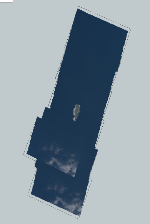
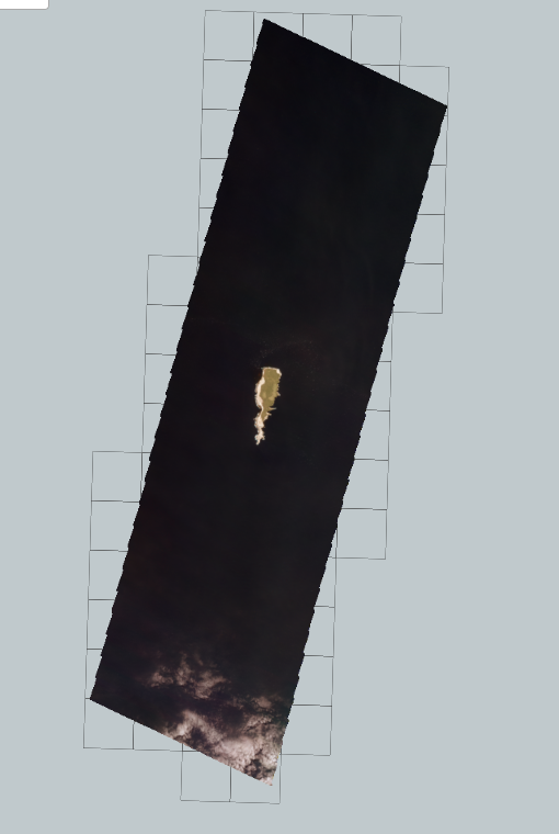
This issue occurs when the bundle block adjustment process fails due to an insufficient number or a poor distribution of Ground Control Points (GCPs) and tie points. This is common in scenes dominated by water or clouds, where the algorithm cannot locate enough reliable features. In such cases, the L1C processor must fall back to using raw satellite telemetry, which can result in a misaligned or "non-straight" image stripe in the final output.
| L1C result | Expected result |
|---|---|
|
|
Blunders
Anomalies are discerned through a distinctive contrast inversion observed in the NIR band relative to others, with a notable tendency for this irregularity to impact road segments in closer proximity to agricultural fields.
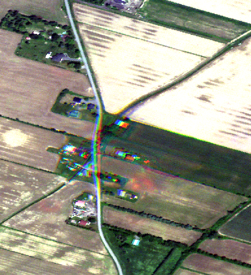 Miss matching effect.
Failure in composition
Eventually the algorithm of composition may fail when creating a composite image. This problem should be isolated respect the surrounding composites, usually due to the need of improving the algorithm with specific image contents. It is expected that this issue will be less likely to be found with upcoming product versions, where the algorithm will progressively get more robust.
 Isolated failure in image composition.
Frame loss during satellite data transmission
Occasionally, between image capture and the download of data from the satellite, one or more frames may be lost. This can result in gaps or discontinuous information in the imagery product. While rare, users should be aware that this possibility exists and may affect the continuity of coverage in some acquisitions.
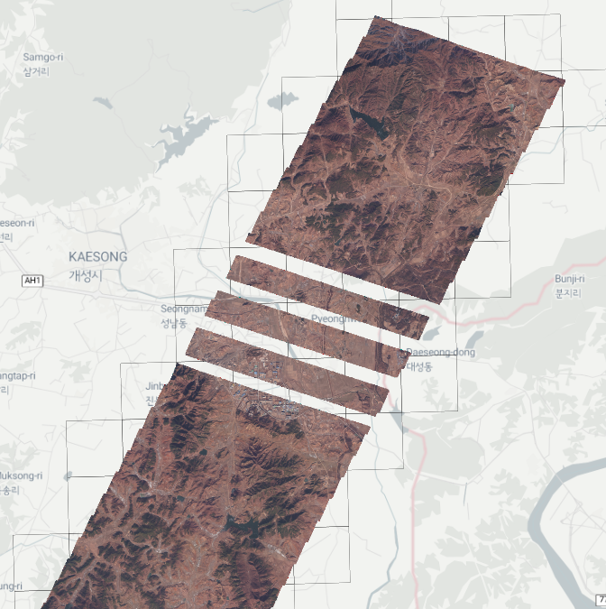 Missing frames.
Changelog
| Version | Release date | Change log |
|---|---|---|
| 2.3.0 | 04/02/2026 |
|
| 2.2.1 | 24/11/2025 |
|
| 2.2.0 | 17/11/2025 |
|
| 2.1.0 | 27/08/2025 |
|
| 2.0.0 | 20/05/2025 |
|
| 1.7.1 | 06/02/2025 |
|
| 1.6.0 | 28/11/2024 |
|
| 1.5.0 | 24/10/2024 |
|
| 1.4.0 | 19/09/2024 |
|
| 1.3.0 | 06/05/2024 |
|
| 1.2.0 | 02/05/2024 |
|
| 1.0.0 | 15/02/2024 |
|
| 0.10.0 | 15/01/2024 |
|
| 0.9.0 | 15/12/2023 |
|
Imagery End User Rights Agreement and Terms of Use
All imagery products are delivered under Satellogic Imagery End User License Agreement. The terms and conditions of the agreement are available to customers and accessible online on the website under License Agreement.