Radiometric Correction
Radiometric correction is done when processing L0 raw frames to L1A Top of Atmosphere frames. The image processing pipeline applies several corrections on the raw data in order to correct for the payload’s radiometric distortion. Two main dimensions are addressed: pixel-wise (spatial variance) and global (spectral variance).
Pixel-wise Correction
The pixel-wise distortion impacts on the spatial variation of the scene. A set of image processing steps are applied in order to correct this, involving:
-
Dark frame subtraction: Dark frames are calibrated on orbit in order to guarantee the exact thermal conditions as in production imagery. Dark frames are obtained by averaging a set of on orbit captures of oceans at night.
-
Flat field correction: Flat fields are calibrated on orbit in order to guarantee the exact thermal and optical conditions as in production imagery.
- Mark IV: Flat fields are obtained by averaging random captures from production imagery, comprising varied terrains and spectral signatures. The input frames are pre-validated in order to discard those with more than 10% of saturated pixels. The average of at least 6000 frames has been proven to guarantee the convergence of the flat field uniformity.
- MarkV: The low and high spatial frequency components of the flat fields are created separately then combined. The low spatial frequency component is generated using desert captures. The images are downsampled and blurred to get rid of small details, then combined. The high spatial frequency component is created using spotlight captures and an in-house algorithm based on Section II of the paper of Caron et al., 2016.
-
Bad pixel filtering: Each pixel is compared with the mean of its eight adjacent pixels. If the pixel is proven to be an outlier, the pixel value is replaced with the average of the neighboring pixels.
-
PSF deconvolution: The PSF of each payload is measured in the lab during the pre launch campaigns. We use this lab-measured PSF to perform deconvolution in order to improve the sharpness of the retrieved imagery.
-
Straylight correction: Image content dependent straylight may cause unwanted color artifacts where the consecutive frames meet (see examples). Our correction algorithm is to mitigate this artifact.
Global Correction
Once the spatial variation of the scene is corrected, a global correction factor per spectral band is applied in order to correct for the spectral response of the payload.
The sensor quantum efficiency along with the filter and telescope transmissivity are measured during the pre-launch campaigns to retrieve the spectral response function and the estimated gain of each payload and band. Using the gain and the exposure time the DN values are first converted to top of atmosphere radiance (\(L_{\lambda}\)).
Top Of Atmopshere Reflectance Correction
The radiance is converted to TOA reflectance (\(\rho_{\lambda}\), adimensional) by applying the equation
where \(L_{\lambda}\) is the top of atmosphere radiance, \(G_{\lambda}\) is the vicarious gain correction described in the next section, while \(M_{\rho}\) is the rescaling coefficient that converts the TOA radiance to reflectance:
$$ M_{\rho, \lambda}=\frac{\pi D^2}{irrad_{Sun} \sin(\theta_{SE})} $$ Here \(D\) is the Sun-Earth distance in Astronomical Units (AU); \(\theta_{SE}\) is the Sun elevation angle at the time and location of the capture; \(irrad_{Sun}\) is the exatmospheric solar irradiance for the sensor at 1 AU, calculated using the the solar model of 2000 ASTM Standard Extraterrestrial Spectrum Reference E-490-00 and the spectral response functions of each payload and band.
Vicarious calibration
The vicarious gain correction \(G_{\lambda}\) is determined via an on orbit calibration process. We ensure the radiometric accuracy of our images by cross-calibrating with Sentinel-2. The main targets used for vicarious campaigns are Railroad Valley Playa (USA), Gobabeb (Namibia), Baotou sand (China), and La Crau (France). We regularly capture these locations for calibration and monitoring purposes. During the calibration campaign we search for Sentinel-2/Newsat image pairs at these locations that satisfy given conditions regarding closeness in time, angular matching criteria, and cloud coverage. The Newsat image is resampled to resolution of the Sentinel-2 image, and both are cropped to a pre-defined region of interest. We calculate the spectral band adjustment factor between the payloads using Radcalnet’s TOA measurements of the given site. The vicarious gain correction is calculated for each pair of images (fitting only the gain coefficient and keeping the bias as zero), and finally averaged.
Geometric Correction
The goal of the geometric correction is to solve, for each of the frames that are used to compose a relevant product tile, fine-tuned values for the position and attitude of the camera at the time when the frame was taken. The solved values is chosen such that the orthorectified images of each frame (when computed based on these corrected values, plus the camera model and the DEM; will match as much as possible both one another and the reference map (as represented by the GCPs that are available in that area). Satellogic’s geometric correction process involves matching of overlapping contents between frames, the matching of frames to GCPs, and fine-tuning the satellite attitude based on this information.
Inter-Frame Matching
Pairs of raw image frames which have been captured consecutively and have overlapping content are matched against each other, and estimates for the transformation functions between these pairs are computed based on these matches. This processing stage produces overlapping frames ready to be further processed.
Frame to GCPs Matching
A major input for the geometric correction algorithm is a set of “matched GCPs” generated for each individual frame using GCPs that were built automatically based on reference maps, which are geo-referenced imagery taken from an external provider. ESRI imagery is currently used at zoom level-17. To generate GCPs, for each region, a large number of candidate features are extracted from the reference maps. Only the features that were matched to relevant Satellogic frames, with matches that pass a set of filters, are used to generate coordinates (Lat and Long) of GCPs from the reference imagery.
For featureful terrain, around 1000 GCP matches are typically found per raw frame (40 matches per square-km). In cases where there is a sufficient number of matches for a given capture frame, a smaller partial set is chosen, which is more evenly distributed over the frame. But in harder cases (e.g. desert, snow fields, open water, dense forest, beaches and islands), matches might be concentrated in specific regions of the frame, which affects the geo-accuracy of the resulting image frames. In some situations, ground control points cannot be matched to the collected imagery, either because the ground is covered by clouds, or because there is no suitable reference imagery to be used as GCP source (e.g. open water). In these cases the state of the spacecraft and camera is modelled and either interpolated or extrapolated and orthorectification is attempted with the approximate geolocation data and estimated position.
Bundle adjustment
At this stage, the satellite position, pointing direction and focal length data at the time of capture are fine tuned. This is done by solving equations that include the inter-frame matches and the GCP matches that were generated in the previous processing. The algorithm also takes into account constraints such as continuity of the positions sequence (satellite positions should lie on a valid earth orbit) and accuracy of the onboard systems (the solved positions and attitudes should be within the uncertainty range, not too far from the measured telemetry data). Note that the solved camera states, together with the DEM, uniquely determine all the information that is required for both orthorectification and image composition. Accurate solutions should result in correct alignment of the different frames, which would manifest as accurate band alignment and smooth intra-band stitching, as well as good geo-accuracy. Therefore, in optimal conditions, this stage is where band alignment is achieved.
Orthorectification
The orthorectification processing solves geometric distortions caused by terrain relief and sensor and satellite position at the time of capture. At this stage, the frames are aligned to a trusted DEM and are projected to a coordinate reference system to create image tiles in a uniform format, which is independent of the particular capture position and camera angles.
Image Composition
Image composition stage involves band alignment and image tiling.
Each individual frame contains 4 bands (blue, green, red and NIR). The goal of this stage is to combine the input frames into a product that has all the 4 bands for each pixel, but with a unique value for each pixel within a given individual band. For efficient resource usage, the product is split into tiles (4096 x 4096 pixel each) that can be independently generated. This tiling is based on the same grid that was used to orthorectify the input frames.
Before the actual composition of each tile, an extra co-registration algorithm is applied if the fine-tuned positions that were solved in the geometric correction stage were not sufficiently accurate. This extra band alignment processing solves the issue by adjusting the positioning of the individual orthorectified frames (based on some more image matching) before actually composing them into the tile.
Super resolution
Super-Resolution (SR) refers to algorithms aimed at increasing the image spatial resolution, which in turn increases the number of pixels but providing fine details in the resulting image as if a sensor with a higher nominal resolution would have been used.
Satellogic applies its proprietary super-resolution model based on Multi-Scale Residual (MSRN) neural network and adapted to Satellogic satellite images in a post-processing step of the native orthorectified product. After the model application which essentially applies a x2 upscaling factor, an image resampling using pixel area relation to bring the output resolution to the final 0.7 m/px for Mark4 and 0.5 m/px for Mark5 satellites and in the same time, it preserves the original radiometric quality (pixel values).
The following are benefits that are achieved with this processing:
-
Denoising: The SR model Increases the SNR of each MS band.
-
Deconvolution: The model uses the learned knowledge to generate the higher frequency details that were lost due to aliasing during the creation of the native 1m images.
-
Zoom effect: The model brings the native 1m images to a synthetic 70cm resolution, uniform across all captures.
Color correction
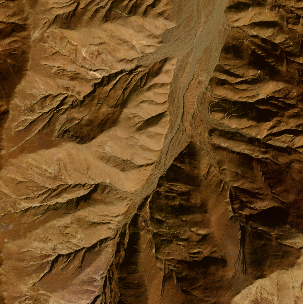
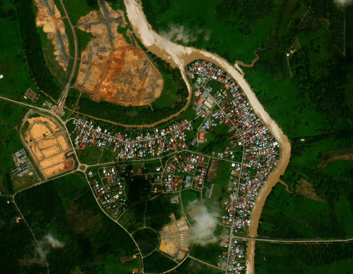
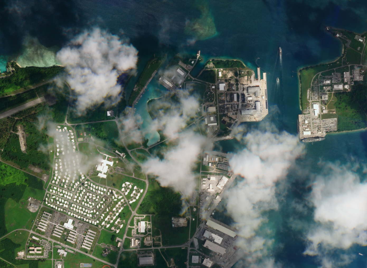
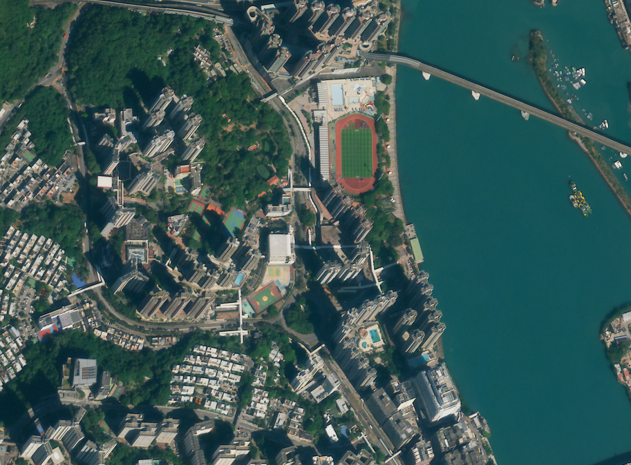
Along with the TOA 16 bits 4 bands (BGRN) reflectance product, Satellogic offers a TOA derived visual product in 8 bits (RGB) for visual applications. The visual product is enhanced for visual purposes with a color curve as well as with some aesthetic adjustments such as saturation and gain to take into account different scattering of the 3 bands (indeed shorter wavelengths are scattered more strongly than longer wavelengths). The method applied is not content-dependent, so the same transformation is applied for every scene. This has the advantage to reduce differences between contiguous captures that could have been caused by a simple histogram stretching, making them more suitable for remapping or avoiding saturation of brights elements (if both are taken under similar weather conditions and angles). On the contrary, some scenes could still have a better aesthetic attractiveness if they were manually adjusted/stretched.
Cloud Masks
Some processing levels are endowed with a cloud mask specifying cloud coverage at the pixel level. Cloud masks are particularly important for ensuring that downstream analysis with Earth observation data are not compromised by cloud interference. This section describes the technique used for cloud detection for the L1B, L1C and L1D processing levels (for L1D_SR, the cloud masks are inherited from the corresponding L1D product).

Cloud masks are computed at 10m resolution. Besides no data pixels for which there is no information, the cloud mask currently provides information at the following levels:
- Clear skies: there is no cloud interference
- Haze or thin clouds: there is cloud but the Earth is still visible
- Thick clouds: Earth is occluded
In the following image, we show a sample of the different categories predicted by the model. The no data pixels are shown in yellow, clear skies are shown in black, haze in grey and clouds in white.
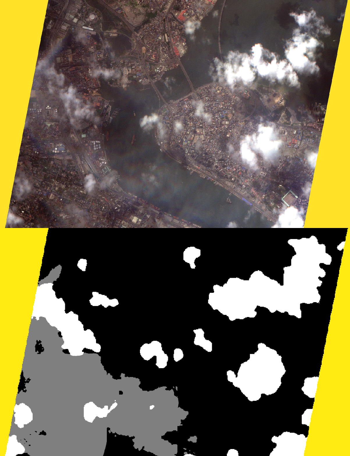
Our model behind the scenes is a deep neural network for segmenting images. In the following we give a general overview of the subproduct and how we compute it.
Mask Format
For each tile or chunk of our products, a cloud mask is provided as a single band GeoTIFF. Each pixel value of the mask corresponds to a different semantic class as follows:
| Class | Value |
|---|---|
no data |
0 |
clear |
1 |
haze |
2 |
cloud |
3 |
Technical Approach
We employ a deep learning architecture designed for semantic segmentation of clouds in our imagery. In particular, the architecture is a U-Net model with a ResNet-18 backbone pre-trained on ImageNet1.
To train the model we have used two large sets of properly annotated data:
- CloudSen12+2, which is a publicly available dataset of images from Sentinel2, providing cloud and cloud shadow manually created groundtruth. It comes in three types of annotations from which we have used the ~10k tiles of
highlabel type. From these images, we take the BGRN bands at 10m resolution for training and only used the semantic classes of our interest. - Around 2k manually curated tiles from our own imagery, at 1m resolution, portraing several situations and cases of clouds.
We use the BGRN channels and train the neural network at multiple resolutions of the images for better learning of context and detail.
The cloud mask for a given chunk is computed at 10m resolution and eventually resampled up to the original tile's resolution with a nearest neighbour strategy.
Cloud cover
The cloud cover value reported in each product metadata is the percentage of cloudy pixels over the set of valid pixels (clear, haze and cloud). In this case, hazy pixels are not considered as cloudy.
Known issues
- Very flat, saturated regions may be regarded as clear pixels
- Snowed areas may be mistakenly taken as clouds
- The detector may perform suboptimally on flat surfaces such as deserts
We keep improving the model by incorporating new data to the training set of images. Feedback on scenes where the cloud detector is not giving the proper answers is more than welcome.