Ortho (L1D/L1D_SR)
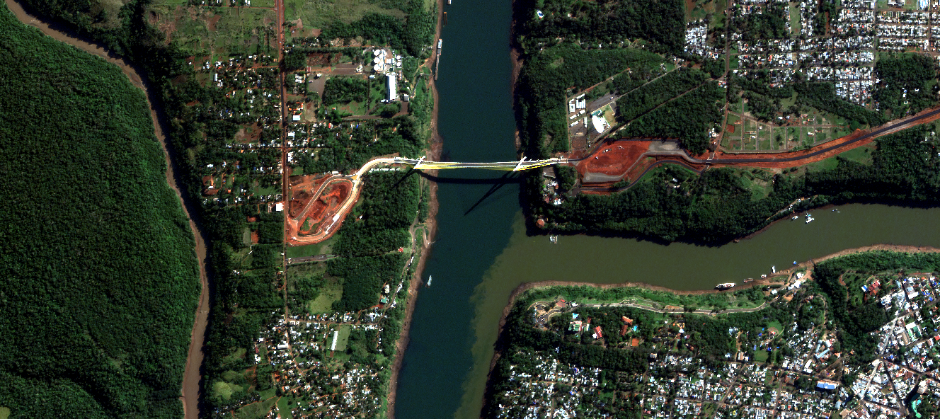
Product description
The L1D and L1D_SR imagery products are 4-band (RGB and Near infrared) product designed for accuracy and best of class image quality. It is delivered to customers after going through radiometric and geometric correction process.
The ortho products are currently offered in two major processing levels:
- L1D TOA Reflectance (L1D)
- L1D TOA Reflectance SuperResolution (L1D_SR)
L1D_TOA, is a 4 bands (blue, green, read and Near Infrared) imagery product with Top of the Atmosphere reflectance records measurements in physical units, and enables analysts to perform basic classifications and analytics. The imagery is radiometrically and geometrically corrected. Pixel values are scaled to TOA Reflectance (0 to 1) multiplied by a factor 10000 (1e4) to avoid float numbers. L1D TOA has a resolution of 1m for Mark IV and 0.7m for Mark V after resampling, which harmonises native pixel size that varies between 0.7m and 1.3m.
L1D_SR_TOA goes through one step further in processing which applies proprietary super resolution algorithm to improve the Ground Sample Distance (GSD) from 1m to 70 cm for Mark IV satellites and from 70cm to 50cm for Mark V satellites.
Both L1D and L1D_SR products are currently delivered along with a corresponding VISUAL Products called L1D_VISUAL and L1D_SR_VISUAL. This is a 3 bands imagery (red, green and blue) derived from the TOA product, processed with a color enhancement algorithm as descibed at section.
The figure below illustrates the high level image processing workflow, which begins upon receiving raw data and is completed after the transfer of processed data to the image catalog and product delivery package:
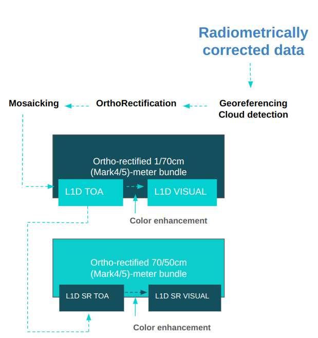
For geometric and radiometric processing details please refer to Image processing section.
Tiles
 The L1D/L1D_SR tiles are available on the Archive STAC API. Each STAC item is a 2km by 2km square tile (plus 1-1.5 meters extra in each direction).
They are aligned to a fixed discrete grid, aligned to the prime meridian of each UTM zone (coordinate 500000m). Each tile has a designated grid code included in the property grid:code as follows:
SATL-<GRID SIZE>-<UTM ZONE> _ <X> _ <Y>
Where X and Y correspond to the easting and northing coordinates of the bottom left corner of the tile.
For example the grid:code SATL-2KM-10N_298_2062 should be interpreted as: - SATL grid of 2km by 2km - On UTM zone 10N - With the left bottom corner at 298,000m easting and 2062,000m northing.
The tiles have an overlap ranging from 2-3 meters with neighbouring tiles in the grid.
Technical Specifications
| Parameter | Mark IV |
Mark V |
|
|---|---|---|---|
| Sepctral bands | Blue : 450 - 510 nm |
Blue : 450 - 517 nm |
|
| GSD | 1m (L1D) / 0.7m for (L1D_SR) |
0.7m (L1) / 0.5m (L1_SR) |
|
| Scene Swath | 4.8 - 5.5 Km 1 |
6.8Km - 8.5Km 1 |
|
| Image bit depth | 8-bit for VISUAL, 16 bit for TOA |
| |
| Max Off-Nadir angle | ± 25 deg |
| |
| Algorithms applied | Radiometric correction, Band Aligment, Fine geolocation, Projection to UTM and orthorection |
| |
| Geolocation Accuracy | 10m CE90 Varies with the availabilty of GCPs and cloud coverage2 |
| |
| Band aligment | <= 2px |
| |
| Image format | GeoTiff, LZW loseless compression |
| |
| Ancilliary files | Cloud mask (GeoTiff), preview (PNG), thumbnail (PNG) and imagery footprint in vector format. |
| |
STAC item
Assets
Non documented files or parameters should be ignored.
All assets follow the same basename template.
{DATE}_{TIME}_{SECOND_DECIMALS}_{SATELLITE}_{PRODUCT}_{PAYLOAD}_{VERSION}_{SUFFIX}.{EXTENSION}
- DATE: Year(4 digits)month(2 digits)day(2 digits)
- TIME: Hour(2 digits)minute(2 digits)second(2 digits)
- SECOND_DECIMALS: All the decimal part from the timestamp seconds
- SATELLITE: Satellite number
- PRODUCT: L1D / L1D_SR
- PAYLOAD: MS for multispectral (4 bands)
- VERSION: Check Changelog. Only present in the metadata asset.
- SUFFIX: depends on the asset, can be empty.
- EXTENSION: depends on the asset type.
All time values refer to the capture time in UTC. Hence the string 20220619_153346_938represent actually 2022-06-19 15:33:46.938.
Raster, preview and thumbnail
Visual
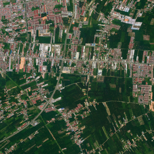
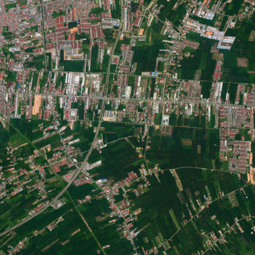
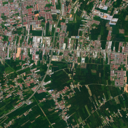
8bits, RGB enhanced version of the original BGRNIR raster. With the same spatial resolution.
Cloud
Cloud masks are provided as single band GeoTIFFs. Check here for details and how masks are computed for L1D product. For L1D_SR, the cloud masks are inherited from the corresponding L1D product and upscaled with a nearest neighbour strategy to the target resolution.

Toa Factors
The L1D/L1D_SR product raster is provided in Top Of Atmosphere (TOA) reflectance units (which take values between zero and one), encoded with a 10000 factor in order to fit them in a standard Tiff file. The conversion radiometric conversion factors are inherited from the input images(L1C) processing level.
Item metadata
| Prefix | Field Name | Description | Example |
|---|---|---|---|
| n/a | id | Unique identifier for the STAC item | 20250930_025801_143_SN45_L1C_MS_2_0_0 |
| n/a | bbox | Item bounding box | [ 119.56896495671906, 23.62805912936759, 119.65730868533569, 23.690097800133774 ], |
| n/a | geometry | Product footprint polygon or multi polygon | {
"type": "Polygon",
"coordinates": [
[
[-59.39745426956545,
-14.839874521738926],
[-59.397653769623574,
-14.857959361744172],
[-59.37906678933578,
-14.858152718581847],
[-59.37886883226247,
-14.840067632759192],
[-59.39745426956545,
-14.839874521738926]
]
]
}, |
| n/a | assets | List of the assets available for a given item | {
"preview": {
"href": "link to the file",
"type": "image/png",
"roles": [
"overview"
]
},
"rpc": {...},
"cloud": {...},
"analytic": {...},
} |
| n/a | collection | Collection name | l1d |
| properties | gsd | Ground sample distance in meters | 0.7 |
| properties | proj : shape | Dimension of image in pixels (Height x Width) | [2861, 2860] |
| properties | grid:code | Satellogic 2x2km grid code | SATL-2KM-21S_242_8356 |
| properties | instruments | Options are MS for multispectral and HS for hyperspectral | ms |
| properties | datetime | Capture time | 2025-09-06T18:43:23.402269+00:00 |
| properties | platform | Satellite name that acquired the imagery | newsat46 |
| properties | proj:epsg | EPSG code of the Coordinate Reference System in which the image coordinates are | 4326 |
| properties | view : azimuth | Viewing azimuth angle. The angle measured from the sub-satellite point (point on the ground below the platform) between the scene center and true north. Measured clockwise from north in degrees (0-360) | 166.1138 |
| properties | view : off_nadir | The angle from the sensor between nadir (straight down) and the scene center. Measured in degrees (0-90). In case this angle cannot be computed, a value of -1 will be reported | 24.9490 |
| properties | view : sun_azimuth | Sun azimuth angle. From the scene center point on the ground, this is the angle between truth north and the sun. Measured clockwise in degrees (0-360) | 72.3332 |
| properties | view : sun_elevation | The estimated sun elevation measured at the target at the moment of the capture. Value in degrees. | 60 |
| properties | satl : satellite_generation | Satellite generation category, mainly to differentiate between MarkIV and MarkV | MarkV |
| properties | satl : outcome_id | The UUID of the entire capture this individual frame is part of | ffbabb4f-3a97-45ec-bca3-0e4d56608c1c |
| properties | satl : valid_pixel | Percentage of pixels that are valid, from 0 to 100 | 100 |
| properties | satl : exposure_sec | Exposure time of capture in seconds | 0.002769 |
| properties | satl : product_name | The product name | L1C |
| properties | satl : last_modified | Timestamp when the product was last processed | 2025-09-30T04:30:38.122305+00:00 |
| properties | satl : transaction_id | Internal processing transaction identifier | l0-pipeline-cw5td |
| properties | satl : product_version | Product Version | 2.1.1 |
| properties | satl : software_version | Internal software version used to process the product | 1.36.1 |
| properties | satl : satellite_altitude | Satellite altitude in meters | 498240.1195991831 |
| properties | satl : ground_lock | Boolean value that indicates if the processor was capable to find gcps at the capture | true |
| properties | satl-qa : qa_software_version | Quality Control project SW version | 2.11.2 |
| properties | satl-qa : snr_blue | Signal To Noise Ratio for the blue band, In case this metric cannot be computed, a value of -999 will be reported | 64.353 |
| properties | satl-qa : snr_green | Signal To Noise Ratio for the green band, In case this metric cannot be computed, a value of -999 will be reported | 56.291 |
| properties | satl-qa : snr_red | Signal To Noise Ratio for the red band, In case this metric cannot be computed, a value of -999 will be reported | 38.133 |
| properties | satl-qa : snr_nir | Signal To Noise Ratio for the NIR band, In case this metric cannot be computed, a value of -999 will be reported | 23.073 |
| properties | satl-qa : burnt_blue | Burnt pixels percentage for the blue band, In case this metric cannot be computed, a value of -999 will be reported | 0 |
| properties | satl-qa : burnt_green | Burnt pixels percentage for the green band, In case this metric cannot be computed, a value of -999 will be reported | 0 |
| properties | satl-qa : burnt_red | Burnt pixels percentage for the red band, In case this metric cannot be computed, a value of -999 will be reported | 0 |
| properties | satl-qa : burnt_nir | Burnt pixels percentage for the NIR band, In case this metric cannot be computed, a value of -999 will be reported | 0 |
| properties | satl-qa : sharpness_fwhm_act_blue | Full Width Half Maximum across-track value in pixels for blue band*, In case this metric cannot be computed, a value of -999 will be reported | -999 |
| properties | satl-qa : sharpness_fwhm_act_green | Full Width Half Maximum across-track value in pixels for green band*, In case this metric cannot be computed, a value of -999 will be reported | 3.675 |
| properties | satl-qa : sharpness_fwhm_act_red | Full Width Half Maximum across-track value in pixels for red band*, In case this metric cannot be computed, a value of -999 will be reported | 3.241 |
| properties | satl-qa : sharpness_fwhm_act_nir | Full Width Half Maximum across-track value in pixels for NIR band*, In case this metric cannot be computed, a value of -999 will be reported | -999 |
| properties | satl-qa : sharpness_fwhm_alt_blue | Full Width Half Maximum along-track value in pixels for blue band*, In case this metric cannot be computed, a value of -999 will be reported | -999 |
| properties | satl-qa : sharpness_fwhm_alt_green | Full Width Half Maximum along-track value in pixels for green band*, In case this metric cannot be computed, a value of -999 will be reported | 3.008 |
| properties | satl-qa : sharpness_fwhm_alt_red | Full Width Half Maximum along-track value in pixels for red band*, In case this metric cannot be computed, a value of -999 will be reported | 2.846 |
| properties | satl-qa : sharpness_fwhm_alt_nir | Full Width Half Maximum along-track value in pixels for NIR band*, In case this metric cannot be computed, a value of -999 will be reported | -999 |
| properties | satl-qa : dr_blue | Dynamic Range for the blue band* *, In case this metric cannot be computed, a value of -999 will be reported | 96.728 |
| properties | satl-qa : dr_green | Dynamic Range for the green band* *, In case this metric cannot be computed, a value of -999 will be reported | 123.545 |
| properties | satl-qa : dr_red | Dynamic Range for the red band* *, In case this metric cannot be computed, a value of -999 will be reported | 150.386 |
| properties | satl-qa : dr_nir | Dynamic Range for the NIR band* *, In case this metric cannot be computed, a value of -999 will be reported | 81.207 |
| properties | satl-qa : cc_blue | Dynamic Range for the blue band* *, In case this metric cannot be computed, a value of -999 will be reported | -999 |
| properties | satl-qa : cc_green | Dynamic Range for the green band* *, In case this metric cannot be computed, a value of -999 will be reported | -999 |
| properties | satl-qa : cc_red | Dynamic Range for the red band* *, In case this metric cannot be computed, a value of -999 will be reported | -999 |
| properties | satl-qa : cc_nir | Dynamic Range for the NIR band* *, In case this metric cannot be computed, a value of -999 will be reported | -999 |
| properties | satl-qa : alignment_ce95_blue | The 95th percentile of the band-to-band alignment error between the green and blue bands is reported in meters, In case this metric cannot be computed, a value of -999 will be reported | -999 |
| properties | satl-qa : geoaccuracy_ce90 | The 90th percentile of the geoaccuracy error reported in meters, In case this metric cannot be computed, a value of -999 will be reported | -999 |
| properties | satl-qa : geoaccuracy_rmse | The root mean square error of the geoaccuracy error reported in meters, In case this metric cannot be computed, a value of -999 will be reported | -999 |
| properties | satl-qa : alignment_ce95_red | The 95th percentile of the band-to-band alignment error between the green and red bands is reported in meters, In case this metric cannot be computed, a value of -999 will be reported | -999 |
| properties | satl-qa : alignment_ce95_nir | The 95th percentile of the band-to-band alignment error between the green and nir bands is reported in meters, In case this metric cannot be computed, a value of -999 will be reported | -999 |
| properties | satl-insights : lulc_snow | Land use/land cover percentage for snow | 0 |
| properties | satl-insights : lulc_urban | Land use/land cover percentage for urban areas | 8.1 |
| properties | satl-insights : lulc_water | Land use/land cover percentage for water | 77.3 |
| properties | satl-insights : lulc_forest | Land use/land cover percentage for forest | 12.6 |
| properties | satl-insights : lulc_bareland | Land use/land cover percentage for bare land | 0.5 |
| properties | satl-insights : lulc_cropland | Land use/land cover percentage for cropland | 0 |
| properties | satl-insights : lulc_grassland | Land use/land cover percentage for grassland | 1.5 |
| n/a | tile_geometry | Tile bounding box | {
"type": "Polygon",
"coordinates": [
[
[-59.39745426956545,
-14.839874521738926],
[-59.39765383942619,
-14.857965685109374],
[-59.37906035733394,
-14.858159109401297],
[-59.37886233153779,
-14.8400677000418],
[-59.39745426956545,
-14.839874521738926]
]
]
}, |
* See Sharpness. Due to the provisional use of a feature mask that may fail to mask textured clouds, the reported sharpness metric should be considered fully reliable only in frames without cloud cover. A proper cloud mask implementation is pending.
* *Detailed documentation pending.
Packaging specification
If delivered as a package scene (via S3, FTP, or Zip download link), an L1D/L1D-SR delivery contains a mosaic of all/a subset of the L1D/L1D-SR tiles that make up that scene. The metadata available in STAC API for the tiles is also combined and included as a JSON file.
Additionally, every L1D/L1D-SR package includes a digital signature to ensure data authenticity and integrity. Each package contains a manifest file and cryptographic signature that allows verification that the delivered data has not been tampered with. Learn more about Digital Signature verification.
.
├── {date}_{time}_{second_decimals}_SN{sn}_{product_name}_{payload}_{task_id}.metadata.json
├── {date}_{time}_{second_decimals}_SN{sn}_{product_name}_{payload}_{task_id}.zip
│   ├── {date}_{time}_{second_decimals}_SN{sn}_{product_name}_{payload}_CLOUD.vrt
│   ├── {date}_{time}_{second_decimals}_SN{sn}_{product_name}_{payload}_footprint.kml
│   ├── {date}_{time}_{second_decimals}_SN{sn}_{product_name}_{payload}_metadata_iso.xml
│   ├── {date}_{time}_{second_decimals}_SN{sn}_{product_name}_{payload}_metadata_stac.geojson
│   ├── {date}_{time}_{second_decimals}_SN{sn}_{product_name}_{payload}_preview.png
│   ├── {date}_{time}_{second_decimals}_SN{sn}_{product_name}_{payload}_solar_and_viewing_angles.geojson
│   ├── {date}_{time}_{second_decimals}_SN{sn}_{product_name}_{payload}_thumbnail.png
│   ├── {date}_{time}_{second_decimals}_SN{sn}_{product_name}_{payload}_toa_factors.geojson
│   ├── {date}_{time}_{second_decimals}_SN{sn}_{product_name}_{payload}_TOA.vrt
│   ├── {date}_{time}_{second_decimals}_SN{sn}_{product_name}_{payload}_TOA.vrt.ovr
│   ├── {date}_{time}_{second_decimals}_SN{sn}_{product_name}_{payload}_VISUAL.vrt
│   ├── {date}_{time}_{second_decimals}_SN{sn}_{product_name}_{payload}_VISUAL.vrt.ovr
│   └── rasters
│       ├── {date}_{time}_{second_decimals}_SN{sn}_{product_name}_{payload}_CLOUD_{chunk_index}".tif
│       ├── {date}_{time}_{second_decimals}_SN{sn}_{product_name}_{payload}_TOA_{chunk_index}".tif
│       └── {date}_{time}_{second_decimals}_SN{sn}_{product_name}_{payload}_VISUAL_{chunk_index}".tif
├── {date}_{time}_{second_decimals}_SN{sn}_{product_name}_{payload}_preview.png
├── {date}_{time}_{second_decimals}_SN{sn}_{product_name}_{payload}_thumbnail.png
└── {date}_{time}_{second_decimals}_SN{sn}_{product_name}_{payload}_VISUAL.tif
Scene delivery is conditional on the geographical extent of its bounding box, with a threshold of 120 kilometers established for the longest side.
- Delivery in a single chunk (below threshold): if the longest dimension of the scene's extent is less than 120 kilometers, the entire scene is presented in a single image file. In the previous table nomenclature, there will be only one chunk N=0. In particular, all standard POIs we offer (25, 50 and 100 square kilometers) are delivered in this manner.
- Chunking via fixed grid (above threshold): if the longest dimension exceeds the 120 km threshold, the scene is subjected to tiling based on a fixed, predefined grid system.
- Hierarchical grid: this system is derived from base $2 \times 2 \text{ km}$ cells (tiles grid), which are aggregated into larger delivery tiles of $80 \times 80 \text{ km}$ (resulting from $40 \times 40$ base cell groups).
- Non-constant segment size: consequently, the size and shape of the resulting output chunks are not constant. The final size of each chunk is determined by how the scene's extent intersects with the boundaries of this fixed $80 \times 80 \text{ km}$ delivery grid.
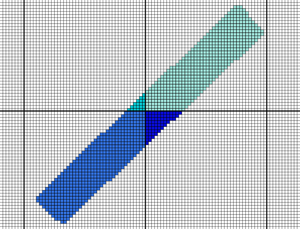
Products are projected to the corresponding coordinate reference system (CRS) according to their closest matching UTM Zone. The projection is indicated in the proj:epsg property of each product metadata. If a scene is captured across different zones, the entire scene is projected to the zone with more data.
Solar and viewing angles
{date}_{time}_{second_decimals}_SN{sn}_{product_name}_{payload}_solar_and_viewing_angles.geojson file contain the tiled information related to the satellite viewing angles, altitude and solar angles.
| Properties | Example |
|---|---|
| satellite viewing angles | {
"azimuth": 88.659999999999997,
"off_nadir": 14.56,
“incidence_angle”: 16,
"units": "degrees"
} |
| solar angles | {
"azimuth": 98.519999999999996,
"elevation": 54.619999999999997,
“zenith”: 46,
"units": "degrees"
} |
| satellite altitude | {
"units": "meters",
"values": 407043.03
} |
Toa factors
The L1D/L1D_SR product is calibrated into Top Of Atmosphere units. Products are in units of reflectance which is a magnitude in the range 0-1. In order to fit them in a standard Tiff file, the 0-1 range is mapped to integers in the range 0-10000. In order to convert it to radiance, calibration factors are included in {date}_{time}_{second_decimals}_SN{sn}_{product_name}_{payload}_toa_factors.geojson file that contain the tiled information about the radiometry transformations.
| Properties | Example |
|---|---|
| toa_to_radiance_units | W / (m^2 . nm . sr) |
| toa_reflectance_to_radiance | {
"blue": 4.776162676561445,
"green": 4.844255590869656,
"nir": 13.011088418320432,
"red": 4.919852418190033
}, |
| reflectance_scale_factor | {
"blue": 0.0001,
"green": 0.0001,
"nir": 0.0001,
"red": 0.0001
} |
*Non documented parameters should be ignored.
Metadata files
Included in the deliverable package we have three different files
Root metadata file
{date}_{time}_{second_decimals}_SN{sn}_{product_name}_{payload}_{task_id}.metadata.json
| Prefix | Field Name | Description | Example |
|---|---|---|---|
| n/a | id | Unique identifier for the STAC item | 20250820_052828_SN40_L1D_SR_MS_310794_2 |
| n/a | bbox | Item bounding box | [ 119.56896495671906, 23.62805912936759, 119.65730868533569, 23.690097800133774 ], |
| n/a | geometry | Product footprint polygon or multi polygon | {
"type": "Polygon",
"coordinates": [
[
[-59.39745426956545,
-14.839874521738926],
[-59.397653769623574,
-14.857959361744172],
[-59.37906678933578,
-14.858152718581847],
[-59.37886883226247,
-14.840067632759192],
[-59.39745426956545,
-14.839874521738926]
]
]
}, |
| n/a | assets | List of the assets available for a given item | {
"preview": {
"href": "link to the file",
"type": "image/png",
"roles": [
"overview"
]
},
"cloud": {...},
"analytic": {...},
...
} |
| n/a | collection | Collection name | deliverables |
| properties | gsd | Ground sample distance in meters | 0.5 |
| properties | created | Deliverable creation date | 2025-09-01T20:04:56.442757Z |
| properties | platform | Satellite name that acquired the imagery | newsat46 |
| properties | datetime | Capture time | 2025-09-06T18:43:23.402269+00:00 |
| properties | platform | Satellite name | newsat40 |
| properties | proj:epsg | EPSG code of the Coordinate Reference System in which the image coordinates are | 4326 |
| properties | providers | Imagery acquisition responsible | [
{
"url": "https://satellogic.com/",
"name": "Satellogic",
"roles": [
"producer",
"processor"
],
"description": "High-resolution geospatial imagery and analytics"
}
] |
| properties | instruments | Options are multispectral and hyperspectral | multispectral |
| properties | satl : task_id | Tasking identifier | 1661138 |
| properties | satl : task_name | Tasking name | target A |
| properties | satl : area_km2 | Deliverable area in square kilometers | 61.3 |
| properties | satl : outcome_id | The UUID of the entire capture this individual frame is part of | ffbabb4f-3a97-45ec-bca3-0e4d56608c1c |
| properties | satl : project_id | The project identifier | 2241 |
| properties | satl : project_name | The project name | project A |
| properties | satl : client_name | The client identifier | client X |
| properties | satl : exposure_sec | Exposure time of capture in seconds | 0.002769 |
| properties | satl : product_name | The product name | L1D_SR |
| properties | satl : product_version | Product Version | 1.4.0 |
| properties | satl : satellite_generation | Satellite generation category, mainly to differentiate between MarkIV and MarkV | MarkV |
| properties | eo : cloud_cover" | Percentage of the image covered by clouds | 6.37 |
| properties | constellation | Satellite constellation | Aleph1 |
| properties | view : azimuth | Viewing azimuth angle. The angle measured from the sub-satellite point (point on the ground below the platform) between the scene center and true north. Measured clockwise from north in degrees (0-360) | 166.1138 |
| properties | view : off_nadir | The angle from the sensor between nadir (straight down) and the scene center. Measured in degrees (0-90). In case this angle cannot be computed, a value of -1 will be reported | 24.9490 |
| properties | view : sun_azimuth | Sun azimuth angle. From the scene center point on the ground, this is the angle between truth north and the sun. Measured clockwise in degrees (0-360) | 72.3332 |
| properties | view : sun_elevation | The estimated sun elevation measured at the target at the moment of the capture. Value in degrees. | 60 |
Geojson version of the STAC metadata
{date}_{time}_{second_decimals}_SN{sn}_{product_name}_{payload}_metadata_stac.geojson
| Geometry attribute | Description | Example |
|---|---|---|
| gsd | Ground sample distance in meters | 0.5 |
| created | Deliverable creation date | 2025-09-01T20:04:56.442757Z |
| platform | Satellite name that acquired the imagery | newsat46 |
| datetime | Capture time | 2025-09-06T18:43:23.402269+00:00 |
| platform | Satellite name | NewSat |
| proj:epsg | EPSG code of the Coordinate Reference System in which the image coordinates are | 4326 |
| providers | Imagery acquisition responsible | [
{
"url": "https://satellogic.com/",
"name": "Satellogic",
"roles": [
"producer",
"processor"
],
"description": "High-resolution geospatial imagery and analytics"
}
] |
| instruments | Options are multispectral and hyperspectral | multispectral |
| satl : outcome_id | The UUID of the entire capture this individual frame is part of | ffbabb4f-3a97-45ec-bca3-0e4d56608c1c |
| satl : exposure_sec | Exposure time of capture in seconds | 0.002769 |
| satl : product_name | The product name | L1D_SR |
| satl : product_version | Product Version | 1.4.0 |
| satl : satellite_generation | Satellite generation category, mainly to differentiate between MarkIV and MarkV | MarkV |
| eo : cloud_cover" | Percentage of the image covered by clouds | 6.37 |
| constellation | Satellite constellation | Aleph1 |
| view : azimuth | Viewing azimuth angle. The angle measured from the sub-satellite point (point on the ground below the platform) between the scene center and true north. Measured clockwise from north in degrees (0-360) | 166.1138 |
| view : off_nadir | The angle from the sensor between nadir (straight down) and the scene center. Measured in degrees (0-90). In case this angle cannot be computed, a value of -1 will be reported | 24.9490 |
| view : sun_azimuth | Sun azimuth angle. From the scene center point on the ground, this is the angle between truth north and the sun. Measured clockwise in degrees (0-360) | 72.3332 |
| view : sun_elevation | The estimated sun elevation measured at the target at the moment of the capture. Value in degrees. | 60 |
ISO 19115-2 Metadata
{date}_{time}_{second_decimals}_SN{sn}_{product_name}_{payload}_metadata_iso.xml
Satellogic adheres to industry standards governing metadata schemas that align with ISO standards. The adoption of ISO 19115 (ISO metadata standard) ensures that information about sensor identification, image extent, quality, spatial and temporal aspects, content, spatial references, distributions, and other properties of digital geographic data are provided in a XML format for customers seeking to integrate Satellogic map-ready orthorectified raster data directly into their workflows. The table below shows the metadata fields according to ISO 19115-2:
| Identifier | Type | Description |
|---|---|---|
| gmd:fileIdentifier | string | Unique file identifier |
| gmd:language | code | Language used for metadata (eng) |
| gmd:characterSet | code | Character coding standard in the metadata (utf8) |
| gmd:contact | string | Contact information of the company responsible for the metadata information (Satellogic) |
| gmd:dateStamp | date | Date of dataset creation in UTC |
| gmd:metadataStandardName | string | Name of the metadata standard used (ISO) |
| gmd:metadataStandardVersion | string | ISO metadata standard version |
| Spatial representation information: grid spatial representation | ||
| gmd:numberOfDimensions | integer | Number of independent spatial-temporal axes (2d: x, y ) |
| gmd:axisDimensionProperties | string/integer | Dimension name (column) and size (integer), resolution (m) |
| gmd:cellGeometry | code | Grid data identification (area) |
| gmd:transformationParameterAvailability | boolean | Dataset coordinates and geographic or map coordinates availability |
| gmd:referenceSystemInfo | string/date | Information of CRS provider, release date, version and edition details |
| Metadata extension information | ||
| gmd:MD_ExtendedElementInformation | string | Exposure time (seconds) and responsible party information (Satellogic) |
| Data identification | ||
| gmd:Citiation_title | string | Name of the dataset |
| gmd:Cititation_Date | data | date in UTC |
| gmd:abstract | string | Scene set identification (Scene set ID) |
| gmd:pointOfContact | string | Contact information |
| gmd:resourceMaintenance | string | Information on dataset maintenance |
| gmd:resourceConstraints | string | The limitations or constraints on the use of or access to dataset |
| gmd:spatialRepresentationType | code | Object used to represent the geographic information |
| gmd:language | code | Languages of the dataset using standard ISO three letter codes (eng) |
| gmd:characterSet | code | Character coding standard in the dataset |
| gmd:environmentDescription | string | Describes the dataset's processing environment |
| gmd:extent | decimal | Information about geographic extent of the dataset (bounding box coordinates) |
| gmd:supplementalInformation | string | Satellogic constellation, satellite name and satellite generation |
| Content info | ||
| gmd:attributeDescription | string | Sensor type |
| gmd:contentType | string | Dataset content type |
| gmd:dimension | string | Imagery bands information (name and wavelength) |
| gmd:illuminationElevationAngle | decimal | Sun elevation angle in degrees |
| gmd:illuminationAzimuthAngle | decimal | Sun azimuth angle in degrees |
| gmd:imageQualityCode | string/date | Metadata standard and version release |
| gmd:cloudCoverPercentage | decimal | Percentage of the are covered by clouds |
| gmd:processingLevelCode | string | Corresponds to data product level |
| gmd:compressionGenerationQuantity | integer | Compression information |
| Distribution info | ||
| gmd:distributionFormat | string | Dataset format name and version |
Additionally, every L1D and L1D_SR package includes a digital signature to ensure data authenticity and integrity. Each package contains a manifest file and cryptographic signature that allows verification that the delivered data has not been tampered with. Learn more about Digital Signature verification.
Known issues
This section lists imagery product anomalies which sometimes slip through the automatic quality assurance filters due different reasons, apprearing clearly different from images that have gone though imagery quality assurance pipeline. The most known anomlalies are explained in this section.
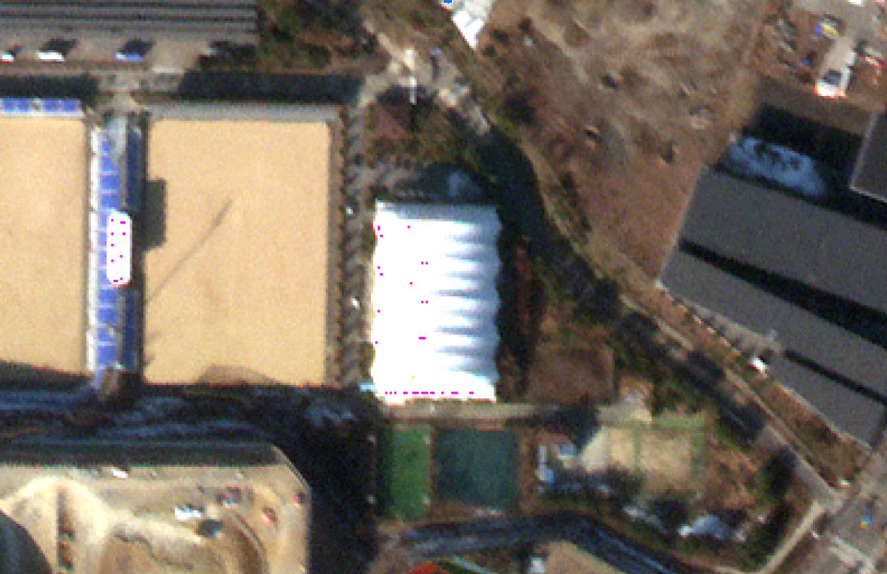
Flipped pixel values in RGB enhanced images
The current image enhancement algorithm causes some flipped pixel values in saturated areas. This will be corrected in future versions of the pipeline.
Reduced geo-accuracy
Some terrain types and environmental conditions might cause the Ground Control Points (GCPs)-based geometric correction to fail, producing captures of lower geo-accuracy. Standard imagery products are delivered with less than 10m geoaccuracy, however, because of high terrain and the lack of GCPs, especially in areas wihtout human made structures such over water, deserts, forests etc., less than 10m geoaccuracy is not achievable, hence some delivered images might show a shift in geolocation. In some extreme cases, such as over open water, such products are marked as a low geoacurracy quality tier and not generaly delivered to customers, but are available on demand for customers who do not have strict geoaccuracy requirements. Some examples are provided below.

Digital Elevation Model (DEM) distortions
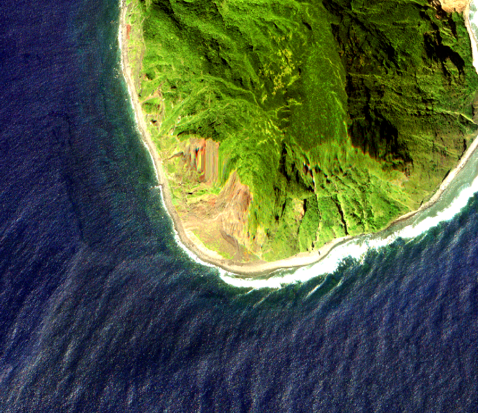
Orthorectified images can present distortions in the presence of outliers in the DEM used during imagery processing. Satellogic is able to detect these problems in the DEM and use alternative models. Occasionally the detector may fail to locate the outliers and produce an effect like the one shown in the image below. This anomaly can be corrected through identifying the outlier in the DEM and reprocessing of the affected scene.
Discontinuities
Discontinuities may also been inherited from L1C processing level
Frame loss during satellite data transmission
Missing frames may also been inherited from L1C processing level
Changelog L1D_SR
| Version | Release date | Change log |
|---|---|---|
| 2.0.1 | 26/11/2025 |
|
| 2.0.0 | 17/11/2025 |
|
| 1.4.0 | 21/08/2025 |
|
| 1.4.0 | 11/06/2025 |
|
| 1.3.0 | 04/06/2025 |
|
| 1.1.2 | 19/12/2024 |
|
Changelog L1D
| Version | Release date | Change log |
|---|---|---|
| 2.2.0 | 04/02/2026 |
|
| 2.0.1 | 19/11/2025 |
|
| 2.0.0 | 17/11/2025 |
|
| 1.2.0 | 12/06/2025 |
Before: Item ids differed only for tile grid number 20250612_075918_430_SN46_L1D_MS_38N_456_4852_1_1_220250612_075918_430_SN46_L1D_MS_38N_472_4848_1_1_2After: Item ids also differ for <TIME>20250617_094442_485_SN28_L1D_MS_42N_740_3616_1_2_020250617_094445_023_SN28_L1D_MS_42N_736_3596_1_2_0 |
| 1.1.2 | 19/12/2024 |
|
| 1.1.1 | 07/11/2024 |
|
| 1.1.0 | 06/11/2024 |
|
| 1.0.1 | 14/10/2024 |
|
| 1.0.0 | 01/10/2024 |
|
| 0.3.0 | 12/07/2024 |
Changed
|
| 0.2.0 | 29/04/2024 |
Fixed
|
| 0.1.0 | 03/04/2024 |
Added
|
Imagery End User Rights Agreement and Terms of Use
All imagery products are delivered under Satellogic Imagery End User License Agreement. The terms and conditions of the agreement are available to customers and accessible online on the website under License Agreement.